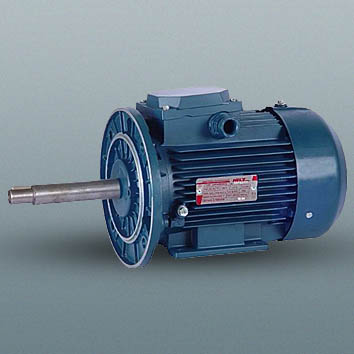
Induction three-phase electric motors for monoblock pumps drive
 The motors are designed for drive of monoblock centrifugal circulating and peripheral pumps in all spheres of industry and agricultural complex, including premises with chemically active environment. The motors are designed to operate with three-phase AC.
- Network frequency – 50 and 60 Hz
- Voltage – 380 V (the motors can be manufactured for other standard voltages on customer’s request)
- Protection degree of motor – IP54 (can be manufactured with IP55 on customer’s request)
- Protection degree of current lead – IP55
- Insulation class – F.
Technical characteristics in case of voltage of 380 V, frequency of 50 Hz
|
Type |
Output, kW |
Rotation speed,
|
Efficiency, % | Cos φ | Мstart
—— Мnom | Мmax
—— Мnom | Istart
—— Inom |
Average noise level, dB(A) | Weight, kg
IM 1081 |
|
AIR 80 А2 G, G2, G3 | 1.5 | 3000 | 81.0 | 0.85 | 2.0 | 2.2 | 7.0 | 65 | 13.1 |
|
AIR 80 В2 G, G1, G2, G3 | 2.2 | 3000 | 82.0 | 0.87 | 2.0 | 2.2 | 7.0 | 65 | 15.7 |
|
AIR 80 А4 G3 | 1.1 | 1500 | 75.5 | 0.77 | 2.0 | 2.2 | 5.0 | 58 | 12.4 |
|
AIR 80 В4 G, G3 | 1.5 | 1500 | 76.0 | 0.80 | 2.0 | 2.2 | 5.5 | 58 | 14.8 |
|
AIR 90 L2 G, G3 | 3.0 | 3000 | 83.0 | 0.90 | 2.0 | 2.2 | 7.0 | 68 | 20.0 |
|
AIR 90 L4 G, G3 | 2.2 | 1500 | 80.5 | 0.82 | 2.0 | 2.2 | 6.5 | 58 | 19.4 |
The following versions are available:
- 1) by mounting:
- combined (IM 2029) - - flange (IM 3029)
- - with special shaft end depending on pump design.
-
- 2) by climatic conditions:
- temperate climate (Y2, Y3)
- tropical climate (T2) - -temperate cold climate (YKhL2) in accordance with governmental standard GOST 15150-69.
-
- 3) special versions:
- chemical stable (Kh2, Y3) - - marine (OM2) for AIR 80-90 G motors (with shaft made of stainless steel).
-
AIR80 G OM2, AIR90 G OM2 are designed for monoblock pump drive, set for operation on Navy vessels in unrestricted navigation area. The motors meet requirements of Maritime Register.
|
Type |
Radial load, N |
Axled load, N |
Weight of parts, which should be mounted on free shaft end, kg |
Weight of parts, which should be mounted on flange, kg |
|
AIR 80 А2, В2, В4, G |
118 |
294 |
4 |
10 |
|
AIR 80 В2, G1 |
324 |
186 |
4 |
10 |
|
AIR 80 А2, В2, А4, В4, G3 |
324 |
186 |
4 |
10 |
|
AIR 80 А2, В2. G2 |
400 |
30 |
3 |
15 |
|
AIR 90 L2, L4, G |
118 |
294 |
5 |
15 |

